
Before you send the RFQ
Treat ISO 2768 as the baseline for un-toleranced dimensions, tolerance each critical feature individually on the drawing, state the datums and inspection condition, and confirm the verification method and report format in the RFQ. Every published value in our case studies is a project-specific requirement, not a general factory limit.
Where a tolerance requirement actually comes from
On a machined part, the controlling document is the drawing. Standards such as ISO 2768 define general tolerances for dimensions where the drawing does not specify a value; they do not replace individually toleranced features. When a bore must mate with a bearing, a cover must seal, or two faces must stay parallel in the assembly, those relationships belong on the drawing as explicit requirements with datums. A note such as ISO 2768-mK on an otherwise untoleranced drawing is a starting point for discussion, not a complete specification for a precision component.
How we read tolerances during drawing review
Our engineering review, led by team members with aerospace-manufacturing backgrounds, reads a drawing in a fixed order: the datum system first, then the features that carry individual tolerances, then the general-tolerance note for everything else. We check whether each specified value is connected to a datum, whether the inspection condition is stated, and whether any value interacts with coating or heat-treatment steps that change the surface. Where a requirement looks ambiguous, we raise it as a question before quoting rather than assuming an interpretation.
What our inspection equipment covers
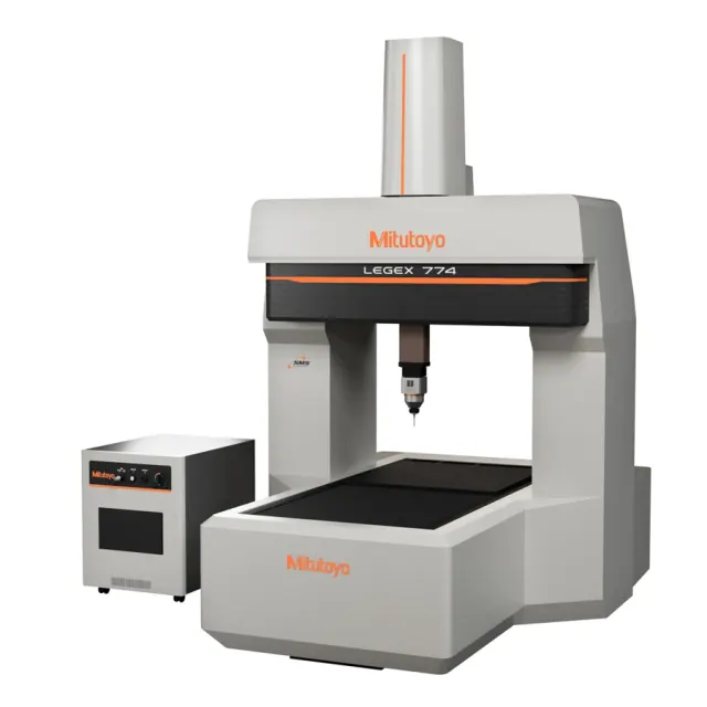
Dimensional verification at NEXUS is anchored by a Mitutoyo LEGEX 774 coordinate measuring machine with a 700 × 700 × 450 mm measuring range. A CMM reports measured geometry against the datums and values the drawing defines; the measuring range describes the volume the machine can evaluate, while the size of a part we can inspect still depends on its geometry and fixturing. Surface roughness and coating-related checks follow the methods agreed for each project. Inspection scope, frequency and report format are part of the quotation, not an afterthought.
What our project records show
The requirements recorded in our published cases show why tolerances are project-specific. The thin-wall enclosure cover specifies a flatness of ≤ 0.05 mm on defined surfaces, checked on 6061-T651 aluminium at 426 × 221 × 36 mm. The rotor-engineering housing specifies a bore coating thickness of 0.15 ± 0.01 mm with Ra ≤ 0.12 µm after HVOF coating and profile grinding. The brass RF housing case records CMM dimensional inspection of channels, mating faces and locating features. These are the values those drawings defined, reviewed part by part; none of them is a general capability limit we apply to every order.
How tolerance decisions affect the quotation
Tighter values rarely change the cutting step alone. A tolerance specified after heat treatment or coating adds process steps; a flatness callout on a thin section drives fixturing and stress-relief decisions; a full-dimension CMM report adds inspection time. Stating which features are truly critical, and which can follow the general tolerance, lets us quote a route that protects the features that matter instead of applying the most conservative process everywhere at the buyer’s cost.
What to specify in your RFQ
Send the drawing with datums and individually toleranced features marked, the general-tolerance standard and class, the inspection condition for any flatness or parallelism requirement, and the stage at which each value applies before or after finishing. Name the report format you expect, for example a CMM report on listed features. If a value is open for DFM discussion, say so; our team can comment on manufacturability while your drawing remains the reference.
| Decision | Why it matters |
|---|---|
| Individually tolerance the critical features | General standards cover un-toleranced dimensions only. |
| State datums and the inspection condition | Flatness and parallelism are only defined against datums and a stated condition. |
| Confirm verification stage after coating or heat treatment | Some values apply to the finished surface, not the machined one. |
| Name the report format | CMM reports, surface-roughness records and coating checks are agreed per project. |
Frequently asked questions
Does ISO 2768 mean a shop can hold ±0.1 mm on every dimension?
No. ISO 2768 defines general tolerances for features the drawing does not individually tolerance. Critical functional features should carry their own tolerance values with datums; the standard is the baseline for everything else.
What tolerances can NEXUS hold on my part?
We review each drawing rather than quoting a blanket number. Where geometry, material and process allow, our route targets critical features in the ±0.01–0.02 mm range; the achievable values for your part are confirmed during drawing review before quotation.
Can you inspect tolerances on larger components?
Our Mitutoyo LEGEX 774 CMM offers a 700 × 700 × 450 mm measuring range. Whether a specific component can be fully verified on it depends on geometry and fixturing, which we review with the drawing.
Do you provide inspection reports with delivered parts?
Yes, with the scope agreed per project: typically a CMM report on the features you list, plus surface-roughness or coating-related records where the drawing requires them.
How do tolerances affect cost?
Tight values can add process steps such as stress relief, grinding, or inspection after coating. Marking only the truly critical features lets the route, and the quotation, stay proportionate.
NEXUS provides drawing-based machining and engineering review. Values in project examples are specific requirements, not general capability limits. The review scope and any proposed changes are agreed with your team.
Discuss your project